In this series of tutorials, we will build a room-temperature monitor with the help of Arduino and Azure. For measuring the temperature, we will use a temperature sensor connected to the Arduino nano board. Then, Arduino will periodically send the temperature values to Azure IoT Hub using the azure sdk c for Arduino and the mqtt protocol. Finally, we will transform this stream of data using Azure stream analytics and create some nice dashboards using Azure Data Explorer, also deployed in Azure.
We will start with only one temperature sensor to simplify the process, later I will add also a light sensor to have more data to play with, but feel free to adapt the code to add more/new sensors. Or even use some mocked data if you don't have any sensor available.
By the conclusion of this tutorial, the resulting solution should appear similar to the following:

All the required Arduino code discussed in this tutorial can be found in this GitHub repository.
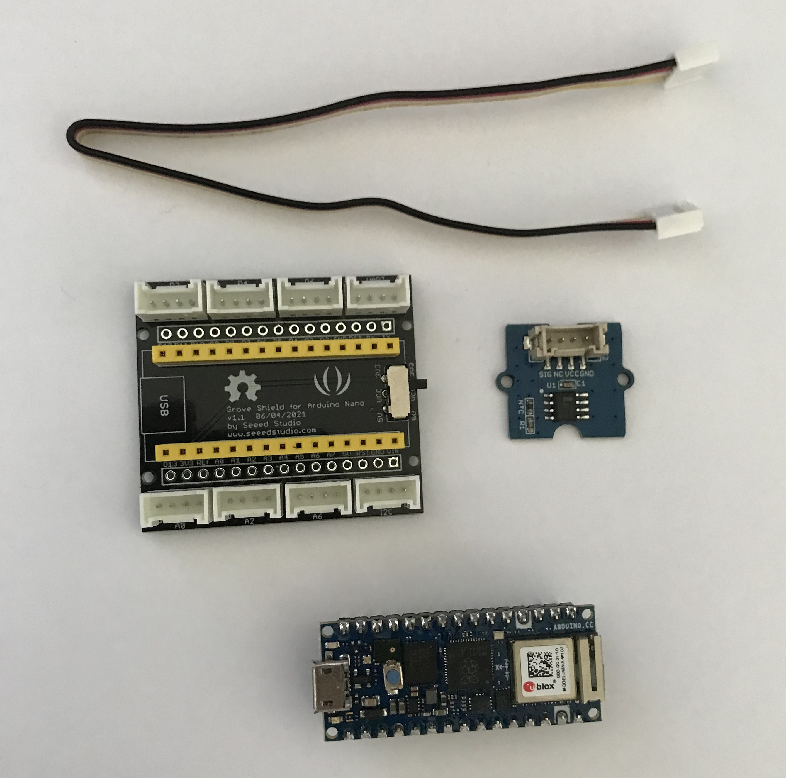
Required Hardware
Important information if you are using the Arduino nano RP2040 with the grove shield
As you can check here there is an incompatibility between the grove shield and the Arduino nano RP2040. The Grove shield was designed for the Arduino nano 33 (and its variants), although being very similar, the pinout is not the same on the nano RP2040. The RP2040 only has one RESET PIN, the other is used for the REC (BOOTSELECT). The GROVE shield has these two pins connected, on the nano 33 it works correctly because they have the same function. But if you try to use this shield on the RP2040 you won't be able to connect the Arduino to the pc, it won't be recognized as a device. So as suggested on the previous link you can just cut the grove shield connection between the 2 RESET pins, you don't have to drill, a sharp knife is enough to break the link.
Nano 33 Pinout
Nano RP2040
Grove shield remove RESET connection link
Hardware setup
If you are using the grove shield the connections are quite easy to do. Just put the Arduino in the grove shield and connect it to the USB port. Then connect the sensor using the grove cable to the A0 pin.
If you aren't using the grove shield, or if you are using another sensor that doesn't have the grove connection, just connect the sensor VCC and GND port to the corresponding Arduino ports and the signal cable to the A0 pin.
⚠️The code I provide in this tutorial is adapted to the seedstudio temperature sensor. If you use another sensor you may have to adapt the code to correctly read its value.
⚠️ Don't forget to move the VCC switch of the grove shield to 3.3V if you are using a Arduino nano (all models).

Some theory before writing code
This section provides a concise explanation of the mathematics behind the code that we will implement later. As the primary focus of this tutorial is Azure IoT, understanding this section isn't crucial; you can skip directly to the next section.
However, if you're interested in learning the details of the sensor readings implementation, please continue reading this section.
Thermistors
The temperature sensor I'm using uses a thermistor to read the ambient temperature. A thermistor is a resistor whose resistance is dependent on the temperature. By measuring the resistance we can calculate the temperature by approximation using one of two formulas, beta equations or the most accurate Steinhart and Hart Equation
Despite being more accurate, the Steinhart and Hart Equation is a bit more complex to implement. Since the objective of this tutorial isn't to have the most accurate temperature measuring I'll implement the Beta equation. We can find the Beta equation on page 6 of the thermistor datasheet. All of the constants required to complete the formula are specified on the datasheet.

| Variable | |
| T | The calculated temperature in Kelvin - The objective |
| T0 | Reference temperature - 25 Celsius in Kelvin - 298.15K - Defined in the datasheet |
| RT | Measured thermistor resistance (ohm), calculated using the voltage divider circuit. Check next section |
| RT0 | Resistance at 25C - (100K ohm) - Datasheet page 11 |
| β | 4250 - Datasheet page 11 |
In the next section, we will see how we can calculate the RT value.
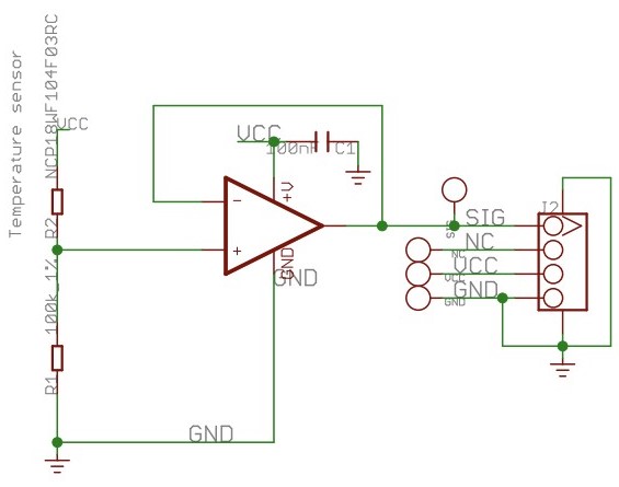
Measure the thermistor resistance
From the previous equation, only the Rt value is missing. This Rt represents the measured thermistor resistance. Calling the analogRead() function reads the voltage on pin A0 and converts it to a digital value with 10-bit resolution, but this isn't precisely what we need. Keep in mind that we require the resistance value (ohms) rather than the voltage (V) measured on pin A0.
Upon examining the temperature sensor's internal schematic, we can observe that it features a voltage divider circuit. With the value of a known resistance (100k Ohm, R1 in the schematic) and the voltage measured at the A0 pin (SIG in the schematic), we can determine the unknown resistance. In this instance, it is the thermistor's resistance, which is the final missing component needed for the temperature calculation formula.
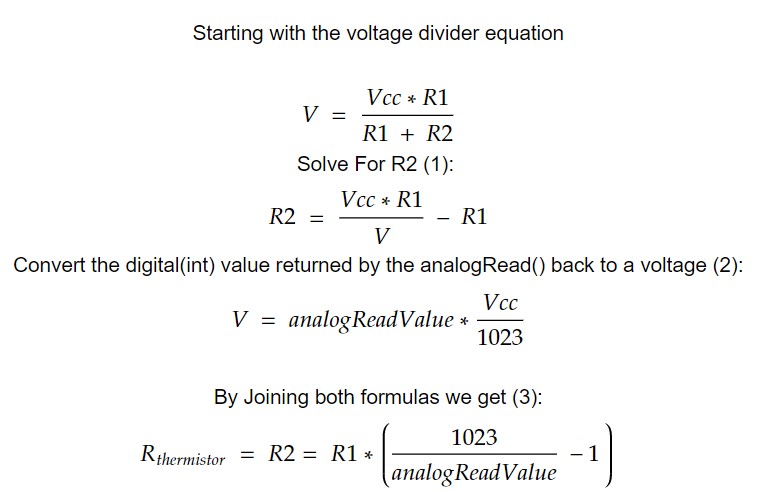
After some math we will end up with the following formula to calculate the value of the resistance of the thermistor:
| Variable | |
| Rthermistor == R2 | Resistance(ohm) of the thermistor, R2 in the schema |
| Vcc | Arduino Vcc, 3.3V for the nano, 5V for the uno |
| R1 | 100K ohm - R1 in the schema, the known resistor of the voltage divider circuit |
| V | Voltage measured on the A0 pin - In the schema it is the voltage measured between SIG and GND. Calculated using the value returned by the analogRead function (formula 2) |
| analogReadValue | The value returned by the analogRead function. An Integer between 0 and 1023 representing the voltage read on pin A0 after the analog to digital conversion. |
With the formula to obtain the resistance of the thermistor, we can implement the beta equation in the Arduino to get the temperature read by the sensor.
Azure Configuration
Before proceeding, we have to create the necessary resources on Azure. For this project we will need the following resources:
Resource group
Iot Hub
Device
To create these resources we can either use azure cli or the web interface, in this tutorial I'll mainly use the web version but I'll document the Az cli commands whenever possible.
Create a resource group
Navigate to Azure resources group page and create a new resource group.
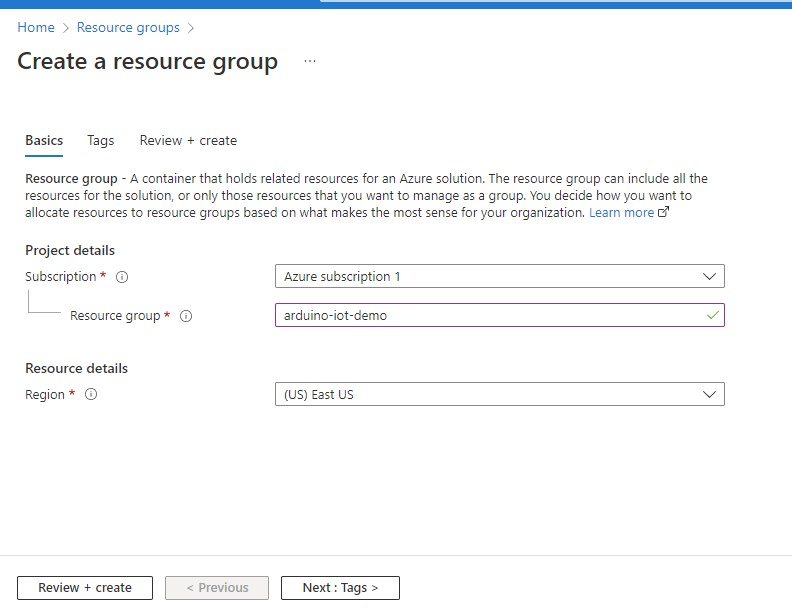
az group create --location eastus --resource-group Arduino-iot-demo
Create IoT Hub
Navigate to Azure IoT Hub page and create a new Hub.

To avoid costs you can choose the Free tier during the hub creation.

az iot hub create --name iot-hub-name --resource-group Arduino-iot-demo --sku F1 --partition-count 2
Create Device
After the Hub is created we must add a new device to it. To do that you should navigate to the newly created hub page, and click on the "Devices" tab.


Get keys to generate the SAS token
To authenticate on Azure Iot the device will need to generate a SAS token, we will see the details later in the code, but for now, you should copy and save the device's primary key.


⚠️Arduino nano rp2040 stores the trusted root certificates on the wifi module hardware. You must install the Azure IoT Hub Root certificate in the wifi module.
If you fail to do so you may get the following error: MQTT connecting ... [ERROR] failed, status code =-2. Trying again in 5 seconds. {{< /admonition >}} {{< admonition type=warning title="Important" >}} These instructions only apply to the Arduinos equipped with NINA wifi modules, for example the nano rp2040. If you want to run this code on another hardware please verify how the root certificates are configured before continuing.
⚠️IoT Hub root certificate migration after 2023
Microsoft will change the Root certificate of all IoT Hubs domains in 2023. Currently, the root certificate is "Baltimore CyberTrust Root", after 2023 it will be "DigiCert Global Root G2". This means that you'll have to repeat this step after the migration, otherwise, your code will stop working.
However, if you want to keep your project running without issues after the migration you can already load the new root certificate. You can fetch it from this domain g2cert.azure-devices.net.
More info here.
Contrary to a typical browser, the Arduino wifi module can't store hundred of Root certificates, you can only store around 10 certificates. So you'll have to pick them wisely according to your project needs. In this case, we only want to connect to azure IoT Hub, so it is enough to add the root certificate of Iot Hub certificate chain.
To install/delete root certificates you have to use the WiFiNina firmware update tool. It is bundled by default in Arduino IDE.
Open the firmware update sketch
To run the firmware update tool you'll have to upload the FirmwareUpdate sketch to the Arduino.

Upload the FirmwareUpdater sketch to Arduino

Open the firmware update tool

Find the hostname associated with your IoT Hub

Install the Azure Iot Hub root certificate on the wifi module
You don't need to download the certificate to your machine. The firmware update tool fetches the certificate associated with the hostname and installs it in the wifi module.

Code Implementation
In this tutorial we aren't going to reinvent the wheel, so we will use some libraries already created specifically for Arduino.
All of these libraries can easily be installed using the Arduino Ide library manager. You should be able to find all of them on the Arduino IDE library manager.

This code cannot be used on other Arduino boards without modifications. The first limitation is the Wifi module. I am explicitly using the WifiNina library, so if you have different hardware for the network interface, you must adapt your code to use the corresponding library. You can find some code samples for different hardware here.
Additionally, I have used some mbed core modules. I am unsure if all boards have the mbed core included or not. I believe it only applies to the Nano 33 boards and the RP2040.
The code to read the temperature from the sensor and upload it to Azure is available in the Github repo. Before uploading it to Arduino you must open the secrets.h file and change the variables accordingly. This file defines the values that are specific to your environment, for example, your wifi ssid and password and the Azure credentials.
#define WIFI_SSID "{REPLACE_WITH_WIFI_SSID}"
#define WIFI_PASSWORD "{REPLACE_WITH_WIFI_PASSWORD}"
#define IOT_CONFIG_IOTHUB_FQDN "{REPLACE_WITH_AZURE_IOT_URL}"
#define IOT_CONFIG_DEVICE_ID "Arduino"
#define IOT_CONFIG_DEVICE_KEY "{REPLACE_WITH_THE_DEVICE_KEY}"
After configuring all the secrets you can compile and deploy the application to Arduino. The easiest way is to use Arduino IDE:
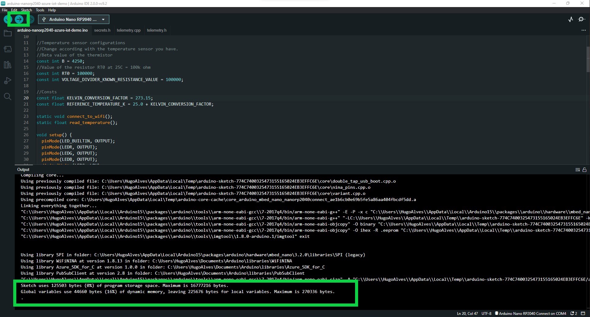
Check that the telemetry is being received by IoT Hub
We can verify if everything is functioning properly by examining the serial output of the Arduino. If all is well, the message "Metric sent to IoT hub" should appear every 5 seconds. In addition to the serial monitor, you can also determine if everything is working by observing the Arduino RGB LED, which should blink green every 5 seconds (each time a metric is sent to Azure). If the red LED begins to blink rapidly, it indicates that something has failed. In this case, you should open the serial monitor to see what is happening.
On the Azure side, we can also monitor the telemetry being received. By executing the following commands in PowerShell, we should start seeing the telemetry data appear in Azure.
$CONNECTION_STRING=$(az iot hub connection-string  show --hub-name ${Replace by your hub name} --output tsv)

az iot hub monitor-events -n "${Replace by your hub name}" --login $CONNECTION_STRING --output table

Next steps
At this point, we have the raw data available in Azure IoT Hub. Now we just need to parse it and start creating useful dashboards with it. This is the objective of Part 2 of this tutorial, where we will use Azure Stream Analytics jobs and Azure Data Explorer to parse and display the data collected by the Arduino sensors.
Common errors
| Error | Solution |
| [ERROR] failed, status code =-2. Trying again in 5 seconds. | Check if the azure IoT Hub root certificate is trusted. |
Code to generate a SAS token in Python. It may be useful if you want to troubleshoot its generation on Arduino. You can run this code locally and then compare the token with the one generated by Arduino.
from base64 import b64encode, b64decode
from hashlib import sha256
from time import time
from urllib import parse
from hmac import HMAC
DEVICE_PRIMARY_KEY = "---"
IOT_HUB_NAME = "Arduino-demo"
DEVICE_NAME = "Arduino"
ttl = time() + 3600
sign_key = "%s\n%d" % ((parse.quote_plus(IOT_HUB_NAME + ".azure-devices.net/devices/nano")), int(ttl))
print("Signature plain text: ")
print("---")
print(sign_key)
print("---")
signature = b64encode(HMAC(b64decode(DEVICE_PRIMARY_KEY), sign_key.encode('utf-8'), sha256).digest())
rawtoken = {
'sr' : IOT_HUB_NAME + ".azure-devices.net/devices/" + DEVICE_NAME,
'sig': signature,
'se' : str(int(ttl))
}
print("SAS token:")
print('SharedAccessSignature ' + parse.urlencode(rawtoken))
References
Hardware:
Azure:
Code related: